 |
DIY on wiring and connections
*Level of the job: 2 (1 to 5, 1 = easy 5 = difficult)
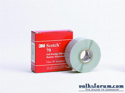
*Required (special) tooling: good soldering iron / station, 60/40 solder, wire stripper, wire cutter *Required parts: good copper wires *Required technical data (think info sheets etc.): none *Estimated time: Once you get the trick, 2 minutes for a good connection. I notice that a lot of people run into questions & problems regarding the wiring of our beloved vehicles. Since our hobby projects are extending more and more into the electronic upgrades, it is of great importance that all connections that have to be made, are made the right way. To start things of i am beginning with a soldered connection in a wiring loom, for example in a dashboard loom. I am using an old Weller Magnastat, an old station discarded at my wife's work for being unsafe because of the open connections :rolleyes: In theory every iron is usable if you are sure that it operates at a constant 370 degrees Celcius. This station is fitted with a sharp tip, suited for small wiring jobs and circuit board repairs, the flattened tips most irons are equipped with are also good to use for wiring. 3 important sidenotes; 1: Solder in a 60% Tin & 40% Lead mixture or, even more desireable 63%/37% mixture, this is eutectic solder, wich means that the solder goes from fluid to solid almost immediatly, better chance on a good connection :thumbup: 2: A good wire stripper and cutter, not those two lying around the shack for years and that where used for clipping the odd nail here and there. Good stuff that works without damaging the wire, i am a fan of Knipex, but most DIY stores offer good quality tools of their own brand these days. 3: Strip your wires down 10mm, more is unnecessary, less is unhandy to work with. First whe tin the end of our two wires. It is ok to have some tin at the tip of your iron, but no big drops please...:shake: all surplus of solder will flow under the isolation because of the capillary action. The flow of solder is good, but you don't want it under the isolation of the wire. Perhaps this is a regulary moved loom and solder under the isolation enhances the risk of broken wires. Both tinned and ready to use, only you really need three hands to do this, but there is a trick, which also provides for a mechanically stronger connection. Strip a wire for 5cm. Take 3 strands of the wire and twist them up. Make a lasso out of the twisted wires, bend the end 90 degrees, wich makes a noose out of it. Put the two wires together and tie them up with the noose until they are firmly together, if the wires are hard to get into this position, use 2. Take the soldering iron, wipe the tip clean, because tin that is allready 5 minutes on your tip is not useable anymore! Hold it against the connection and add a little tin and....ready!!! At the moment you retract the tip from the connection it's important to cool the connection asap, so blow at it, so that the tin goes to a solid state fast. If your connection looks shiney like the one above, it's good. Cut the rest of the noose as short as possible. In a loom this is the best way to finish your connection; heat shrink. In places were there is severe mechanical rubbing or shaving you can add self fusing tape.  That is a non-sticking tape, that fuses together into one layer of rubber. Gives good mechanical strength and protection. Available in different sizes, colors and from multiple brands. Be advised that the fumes that are released with soldering are NOT good for you, no matter how much you like the smell of resin-cored solder...:thumbup: In the next episode i will be explaining how to make crimp connections :thumbup: |
Crimping connections
*Level of the job: 1 (1 to 5, 1 = easy 5 = difficult)
*Required (special) tooling: crimping tool, wire stripper, wire cutter *Required parts: good copper wires *Required technical data (think info sheets etc.): none *Estimated time: Once you get the trick, minimal time involved. This time i will show how to make a good crimp connection, most of us will have made one allready, but i am going a bit deeper into the details of making a good connection that lasts. In my work as a (former) car mechanic i have seen burnt out dashboards, faulty ECU's and a whole truckload of mallfunctions all thanks to radio's or that set of foglights being pinched in an existing wire loom with bad connectors, bare wires just twisted together and isolated with tape; some people should be ashamed of themselves :mad: Roughly, this is what you need: Wire stripper, wire cutter, crimping tool, crimp connectors (or AMP's) Extra's: digit tape, insulation tape, heat shrink The samples used are 0.75mm2, 1.5mm2 and 4mm2, commonly used in cars. The subject of tonight; the connectors. On the left the model of a manufacturer who clearly got the message, made of aluminium, with a barrier installed to point out how far the wire should be inserted. On the right a cheaper model with a harder plastic as insulation, made of tinned copper and without a barrier. Both models are up to the job, but there is a difference in price and durability :rolleyes: Strip down a wire +/- 10mm and try the application, some connectors need more, some less. As the wire is stripped, you do NOT touch it anymore, no twisting up the strands etc. Twisting it up will cause the connector to have less grip on it and the connection will be less dureable. The wire that i am using here is the absolute minimun for this connector; 0.75mm2. Roughly said half the max wire thickess can go in a connector; max wire thicknesses are - red 1.5mm2 / blue 2.5mm2 / yellow 4mm2 (AWG18 / AWG15 / AWG11) The crimping tool; good to see here that this is a double pinching tool, one for the insulation, one for the wire. Tools that only pinch one time and require two seperate pinches are absolutly unsuitable for a good connection ;) Crimp the connector and here is the result above, shaped as a half infinity sign, with max contact between wire and connector. 3 examples of crimped connectors, the tool visibly leaving a mark on the insulation, you know it was done right :thumbup: For use outside the passenger compartment, this is my way to finish them; When (expensive) waterproof connectors are not in your budget or unavailable, i recommend to totally soak them in vaseline (acid-free) and to put heat shrink over the connection, it will last :thumbup: Sometimes, escpecially on oldtimers, the copper of a wire can see totally blacked out, no solder will flow and no other means of connection are possible, that is when i turn to this connector: My supplier calls this the "duraseal" and no they are not cheap...in basic it's a standard connect-through item, but the shell has a suprise to it...:D The proces of use is the same, strip the wire, insert both sides and crimp, nothing fancy so far, but then you take a torch or paint stripper and heat it from the middle section outwards. Inside the tube, that is actually a firm heat shrink, is an amount of wax that is released as the tube shrinks :D You keep heating until the tube is shrunk all the way and wax comes out both sides of it, the connection is now waterproof and ready to go. It is a verry expensive connection compared to a normal crimp connector, but some circumstances ask for this to be used ;) When cutting up a big loom, this is a handy piece of kit; digit-tape, going from 0 to 9 you can assign avery wire a number and run even the biggest wire job down to a simple follow through :thumbup: One last remark on working with terminal bloks and stranded wires, stranded wire under a screw will allways damage the strands an cause resistance in time, resulting in the built up of heat and, at high current, fires, therefore allways use a decent ferrule when working with terminals and non-solid (aka stranded) wires :thumbup: |
The horror pictures...
I know it may sound a bit naggy from my side, but as a certified electrical and instrument technician i know the results of resistance in current paths;
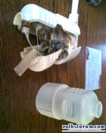
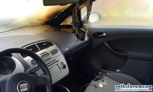
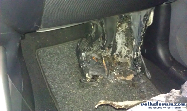
  This is from a simple tumble dryer connected via a 16A rated connection... The dryer was only rated 10A When the amps go up, the damage also does; This is from a 100A rated electric motor, the motor control field had not been taken apart for years and just a little corrosion is enough to cause this... The melting point of normal copper is above 1000 degrees Celcius :cool: You can see here how it's done right; A motor capable of drawing 180A continuous current being connected, with good clean copper that makes maximum use of the surface. Beware that although the voltages in a car are low and seem safe, a fire is started in a blink of an eye and not just the old cars suffer those problems, a dutch forum member found his young Seat with a burnt out dash one morning;   The extra electric heater had commited an act of self combustion and although the 40A fuse popped out, the car's dash burnt out....:eek: The result was a total-loss :mad: |
I am an electrician (trained in Holland in the late 50's).
I have been wiring up spare batteries in my VW Caddy and found your posts very good. Would you mind if I refer to your posts in my Websites and Forums? Thank you very much. Dank je wel. |
Thanks for sharing this wonderful info
|
| All times are GMT +1. The time now is 19:26. |
Powered by vBulletin
Copyright ©2000 - 2024, Jelsoft Enterprises Ltd.